Architect: Smart Design Studio
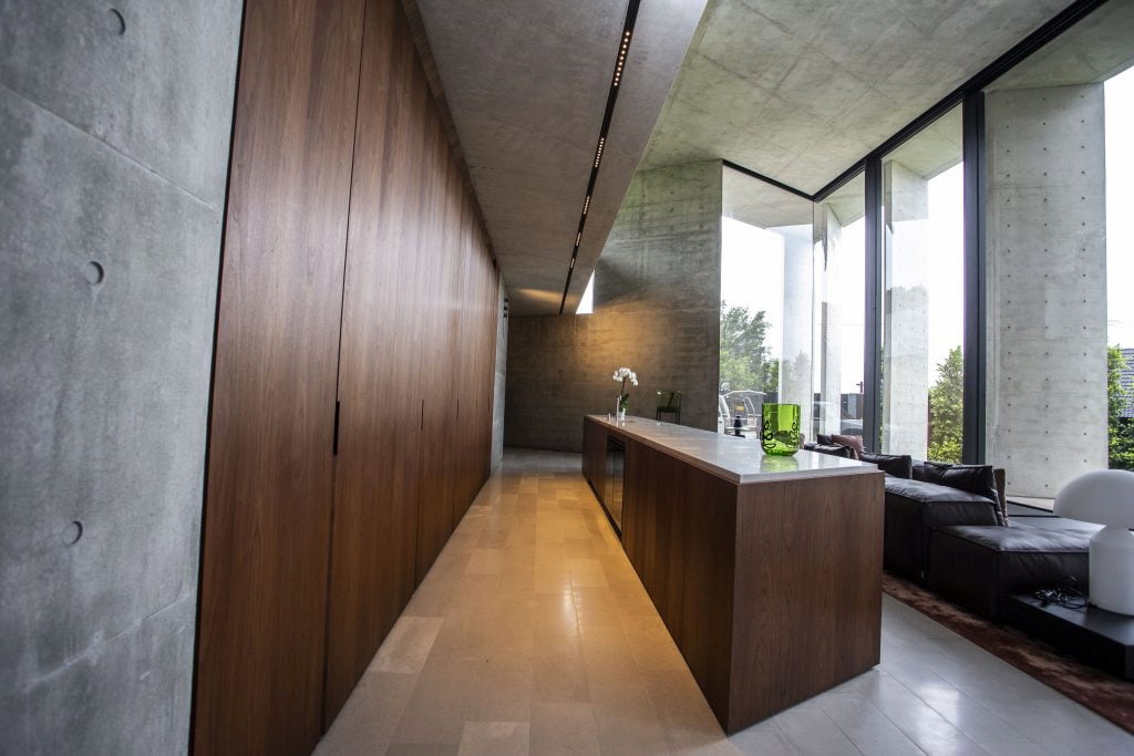
Mosman House is a domestic, residential project that was effectively three projects in one. The undertaking involved the significant renovations and “alterations & additions” to a grand old mansion, the construction on the adjacent property of an all-new pavilion/residence featuring exceptional and ornate off-form concrete throughout, and the construction of a new tunnel and underground passage to link the new pavilion to the original house. This tunnel link required that the original house be underpinned and supported whilst excavations came up and underneath the house, eventually linking in with the old subterranean wine-cellar.
The project came about after the Client (owner of the original mansion) purchased the neighbouring adjacent property, which then became the site for the new pavilion. Architects for the project were Smart Design Studio, and construction was by Sandlik Constructions. Engineering design and documentation for the project commenced in February, 2015. Construction on site commenced in December, 2016 and the project was completed in February, 2019.
Project Brief & Partridge’s Response
The project brief came in the form of preliminary architectural drawings (plans, elevations, and rough sections), and the verbal instruction from the architect that off-form concrete would be the hero and focus of the design. It was further communicated to Partridge that the concrete’s design and construction was to showcase “best practice” and display the highest level of finishing and detailing possible. This came with the additional request that construction and control joints were to be minimal; that any joints absolutely required were to be invisible; and that shrinkage cracking and other such visible defects would not be acceptable.
The first dilemma and challenge for Partridge was to marry up and plan how to achieve these two seemingly conflicting requests: Control joints and construction/pour joints are the best and most reliable tools to mitigate and avoid shrinkage and cracking of the concrete, yet these valuable tools were being denied us.
The second challenge for Partridge was to achieve the above objectives, whilst simultaneously achieving the designed architectural form! The ambitious architectural design featured long spans for the slab and beams which were suspended over the large, open floor spaces, together with some long and formidable cantilevers. Owing to architectural constraints and imposed height limitations, many of the primary concrete spanning elements were tremendously squeezed for depth, thus reducing their potential strength and stiffness.
Partridge’s response was three-fold and involved the following actions and strategies:
- We entered into an extended dialogue with the architect as the various options and approaches for the concrete elements were explored together. Some of this involved educating the architect as to the risks and dangers of pouring extensive concrete elements without joints; waterproofing; colour variation; detailing of sharp corners; slenderness and deflection issues; and so forth.
- We contacted and spoke with concrete contractors to learn and confirm realistic strategies for maximum pour and finishing extents in a day; strategies for minimising batch variation; and formwork/finishing techniques to achieve optimum off-form finishes. We also researched and spoke with concrete suppliers to investigate prescriptive concrete performance mixes that would minimise anticipated shrinkage strains and subsequent cracking.
- We undertook preliminary design, calculations and sketches to determine and communicate structural depths; minimum dimensions for slabs, beams, and columns; deflection limits; detailing for crack control; detailing for pour breaks and waterproofing; and a continuous cycle of “to-and-fro” meetings and communications with the architect to resolve all pinch-points as the evolution of each party’s design responded to the other’s.
The Design & Construction Process
The design and construction process involved an unusually high level of dialogue and co-ordination with both the architect and the builder. Most aspects of the architecture “pushed the envelope” in terms of the concrete’s capacity and capabilities – that is, each element’s ability to satisfactorily span the long distances between supports, without deflecting excessively or cracking. This was exacerbated by the concrete having to perform significant origami in places, owing to folds, rebates, and significant recesses notched into the beams or slabs at critical zones of high stress. Whilst the majority of design work was completed & documented prior to the builder mobilising on site, a not-insignificant amount of design, sketches, and instructions was undertaken and delivered during the build, as a result of architectural changes and to accommodate pour sequences and lead times for the more bespoke steel and reinforcing elements.
A further site constraint on the project was the limitation of height and thus the structural depths and floor zones available for us, as engineers, to utilise. The datum Reduced Levels (RL’s) for the Lower Ground, Ground, and Roof levels were all set by the architect at DA stage, and were “guessed” without first seeking input or advice from an engineer as to the likely structural depths for the beams and slabs. These RL’s could not be adjusted (even through Section 96 submissions to Council), and thus the levels constrained and locked in the maximum depths available for any structure. The architect would not compromise on ceiling heights in the tunnel or to the Lower Ground Floor areas under the lawn. Further structural depth was lost due to the requirement for thick polystyrene insulation panels to be placed between the top of the concrete lid slab and the overlying lawn – noting that the lawn also had to have a minimum depth to function and survive.
As a result of these constraints, the slabs and beams were shallower than an engineer might ordinarily have been comfortable with. Whilst strength was generally not a problem for the lid slabs over the tunnel and Lower Ground Floor, stiffness was the main concern, and so unique detailing of reinforcement and additional steel in the slab was utilised to boost the stiffnesses where necessary.
Creativity & Innovation
Creativity and innovation were required in most aspects of this project. The concrete’s capacity was pushed to the envelope in many places (both figuratively and literally, noting the stresses and high stiffnesses required), and few, if any of Partridge solutions came “out of the box” or relied on standardised details. Bespoke steel columns were conceived and fabricated for the glazing columns; concrete had to be detailed and reinforced to accommodate deep recesses and rebates in areas of high stress and the slabs and beams were analysed, shaped, and reinforced in ways not seen or encountered previously.
Sustainability
The project addressed sustainability across several fronts.
- Hydronic heating was employed in the slabs-on-ground. The concrete was thickened and the reinforcement increased to accommodate the pipes whilst still mitigating shrinkage and cracking, but this facilitated a far greener and less energy-demanding technology for heating the large volume, open plan, double height areas of the pavilion.
- Low-E glass was employed for the glazing, and the pavilion’s design and layout was significantly changed post DA (requiring a Section 96 application) to rotate the pavilion by 15 degrees to provide better solar orientation and thus provide both natural light and heating.
- A green roof (garden lawn) was incorporated into the roof of the pavilion, adding to and improving the insulation to the structure; and large portions of the Lower Ground Floor were subsequently built over, insulated with polystyrene, and covered with lawn. Both areas and elements utilise recycled water and rainwater tanks for irrigation purposes.
Built Environment & Heritage
The new pavilion is a stand-alone structure and piece of architecture that celebrates concrete and introduces a modern and striking addition to the domestic streetscape in this part of Mosman. Being seemingly separate to the original mansion, it provides a striking contrast. The combined estate presents and celebrates both the old and new.
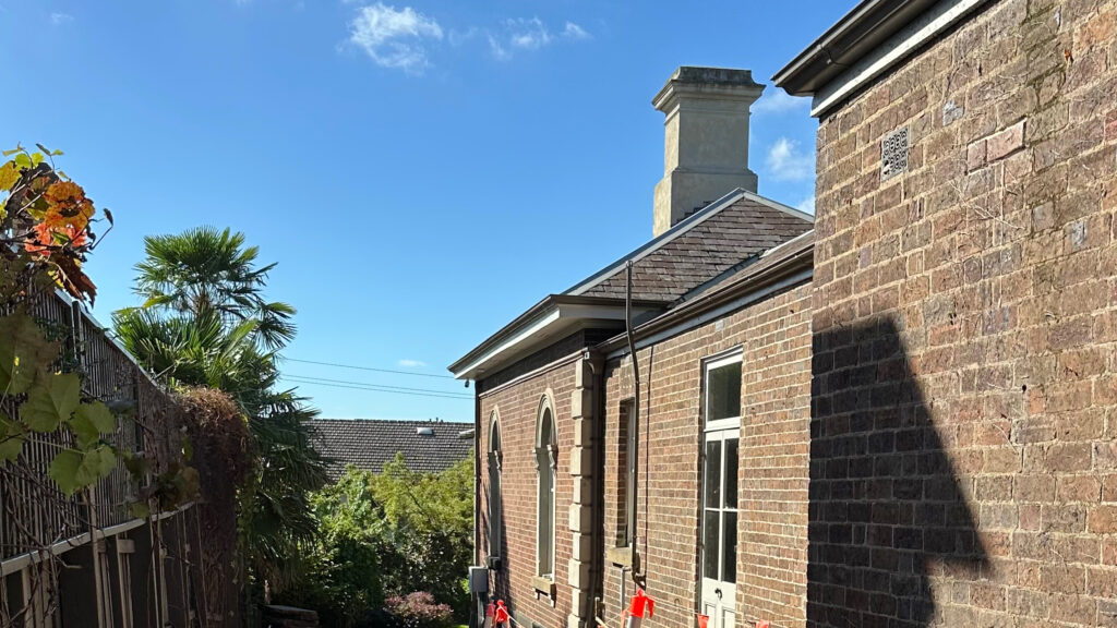
As for the mansion, a major tenet of the architecture, structural design, and construction was to return the exteriors to their original form and not just preserve but restore the building’s heritage. This carried through to the original separate garage building, with tremendous work by both Partridge and a Master Mason to preserve and highlight the original brick arches, whilst simultaneously re-framing and re-supporting the new roof and building components onto the arches without the strengthening and framing elements being visible.
Lower Ground Floor of the Pavilion
The Challenges & Solutions
In a project that comprised three separate projects in their own right (the Mansion, the Pavilion, and the Tunnel), we drew attention to the following specific items:
a) Concrete Beam GCB1
The biggest challenge on the entire project (and arguably the most impressive engineering feat) was the beam “GCB1”. This beam was required to perform the following tasks, subject to the constraints and difficulties outlined:
- It had to span 14 metres, simply supported.
- It had to support the Ground Floor slab, plus the overlying lawn, plus the accompanying live loads.
- It had to support the entire western edge of the suspended Roof slab above, which – in turn – was also supporting a green lawn (i.e. deadweight of saturated soil). The roof slab was transferred on to Beam GCB1 via a series of flat plate steel columns.
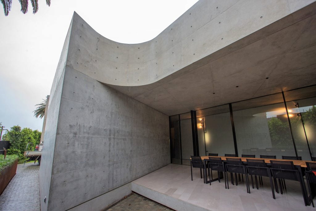
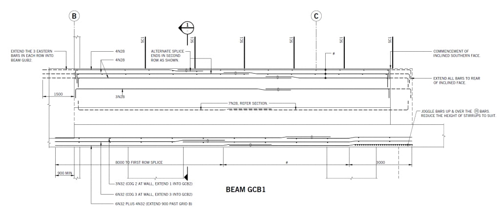
- The beam did not actually land on anything at its southern end! Rather than sit or land on a column or wall underneath, the beam ended sharply over an open corridor underneath. The ultimate end reaction (an enormous load of 1025kN or 105 tonnes) had to be taken out in the Ground Floor slab. To exacerbate matters further, this portion of load-resisting slab featured a 60mm deep rebate in its soffit to accommodate a recessed lighting strip, thereby reducing the strength and stiffness of the slab at the critical section. (Seen in Figure 1)
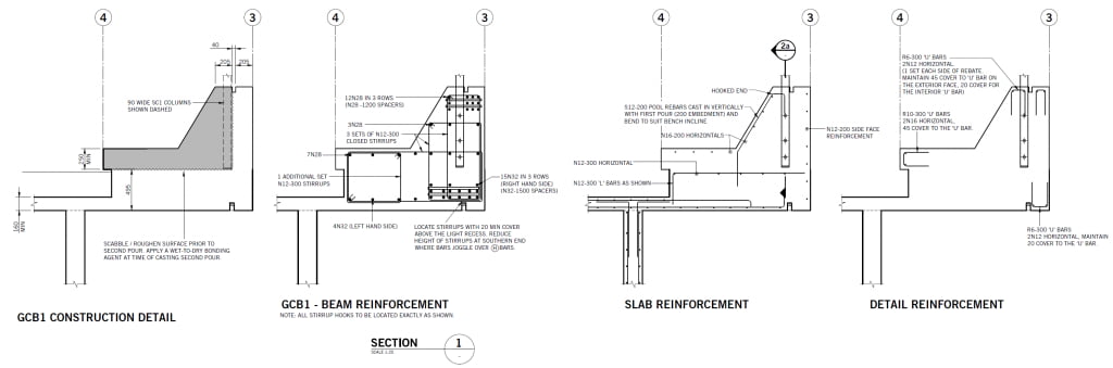
- The beam straddles both the interior and exterior of the pavilion, doubling as a benched seat to the outside lawn, and as a continuation of the internal western wall of the pavilion. It had to be cast in two separate pours with a construction joint running both horizontally and vertically through it. The slanting bench seat made the beam’s profile difficult to model and analyse.
Lower Ground Floor of the Pavilion
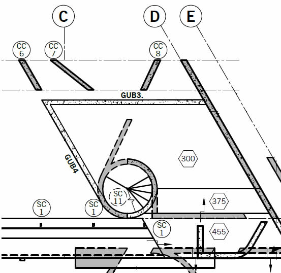
b) The cantilevered Gym slab
The Ground Floor to the Pavilion features a suspended gym off the lawn area. The gym’s geometric shape comprised a large triangular floor plate that showcased a two-way spanning cantilevered slab, with the two cantilevering sides measuring 5m and 4m respectively! (Refer Figure 2). Each side of the cantilever featured an upstand balustrade. We made earnest attempts to get the eastern upstand (GUB3) to work as an outrigger beam, although as can be seen in Figure 2, its springing point was located over a door opening and thus did not have an end support off which to cantilever. In the case of the northern upstand (the 5m cantilever, tagged GUB4), the end of the beam continued into a curved concrete wall which formed the spiral stairs leading from the Gym down to the Lower Ground Floor. As this was the only possible supporting mechanism in the vicinity, we thus cleverly detailed the reinforcement in the upstand to bend and curl into the curved concrete wall, thus providing end anchorage for the cantilever. The curved stair wall then subsequently had to be anchored into deadman footings into the underlying rock below to provide the sufficient resistance to uplift.
As the shape of the two-way cantilever was irregular and the final engineering solution was a complex design that did not fit a standard approach or model, the slab and its cantilevers were analysed, designed, checked, and detailed using three different methods, and we then determined the “best fit” between the results of each method. These methods were Extensive hand calcs, a finite-element model using non-linear analysis, and a Spacegass model using 2D analyses.
The beam was documented in elevation by “unfolding” the curved wall. In order to provide greater resistance and to prevent the joint from “opening up” if the cantilever drooped, we detailed additional inclined reinforcement at the knee joint – a rarely seen detail and solution these days. The regular shear ties were cleverly transitioned to a smaller bar diameter and shrunk to an “inner” location, thus allowing the inclined ties to take an “outer” position. (Refer Figure 3).
c) Curved stairs and joints
The link tunnel that connects the Pavilion to the neighbouring house had to come up via the old subterranean wine cellar. The tunnel needed a new lid slab for the portion of the tunnel that was outside the house, yet the architectural alterations and additions to the house required that a Ground Floor stair exit be located directly above the tunnel. This introduced a difficult piece of detailing where the roof or “lid” of the tunnel had to curve up for architectural effect, whilst having a second portion of stair slab “fly over” the top of it. This introduced significant waterproofing and insulation issues, which required significant detailing and planning with the builder to resolve. The final solution required three separate concrete pours to achieve the desired result. (Refer to Figure 4)
d) Concrete detailing and crack control
As outlined earlier, a major feature (and engineering constraint) on the project was the architect’s insistence on minimal joints and no visible cracking, despite the vast majority of the structure being off-form concrete. Partridge worked closely with the builder and with concrete suppliers to establish concrete mixes with reduced shrinkage strains, and carefully calculated and detailed reinforcement to further resist those strains and subsequent stresses. The architectural detailing to the concrete edges featured unusual and decorative rebates, chamfers, and other shapes that subsequently required bespoke reinforcement detailing to ensure strength to the edges (i.e. no feathering or breaking of the concrete at door/glazing jams). An equally impressive achievement is that there is not one visible joint anywhere on the job where the slab intersects with the external walls – the walls were cast first, with dowels left behind to connect to the slabs in subsequent pours. As a result of all this, steel reinforcement ratios were generally higher than what might typically be the case for domestic construction, however, the work and expense was justified, noting that no significant shrinkage cracking occurred – even with several pours being carried out in the heat of summer.
Owing to the site’s close proximity to salt water, Partridge’s design and detailing also ensured adequate cover to the reinforcement, in order to ensure the long-term durability of the concrete. Hot-dipped galvanised reinforcement was utilised in critical areas to assist in this regard.
It should also be noted that, despite Partridge’s recommendations, the architect declined the use of waterproofing admixtures to the concrete, on account of concerns regarding discolouration and blotching to the final finish. This increased the pressure on Partridge to achieve crack-free solutions, as there were no additives in the concrete matrix to prevent the egress of water. With many of the concrete elements now one to two years old, and the bulk of early drying shrinkage having occurred, QA inspections undertaken in February, 2019 have revealed our efforts were successful.
Final Words
In architectural circles, off-form concrete is enjoying a renaissance at the moment, particularly in domestic residential applications. As engineers, it is gratifying that the structural element becomes the architectural finish. However, off-form concrete is also the most challenging and daunting material to work with, as it most readily displays and betrays any faults and defects: Shrinkage cracking (in its many forms); ferrous staining from rusting steelwork; honeycombing due to poor placement techniques; colour variation due to batch production; and feathering at sharp edges. And that’s before performance defects emerge, such as flexural cracking, deflections, shear, and other mechanisms as the elements are loaded up and resist their loads. Such issues are daunting enough when designing a regular building; they are compounded tenfold when designing a highly irregular building that will become someone’s home.
In spite of these challenges, Partridge successfully delivered not just a building, but a valued engineering service as we worked to achieve the architect’s demands and vision. Collaboration and co-operation with the builder was also paramount to the project’s success, and it was a project that demanded long contact hours, innovative thinking, clever design, unique detailing, and a high level of site-presence. The Mosman House was an all-round effort in excellence in engineering, with the final product serving as ample testament to this. We invite you to view the additional photographs and illustrations on the A3 sheet accompanying this submission.
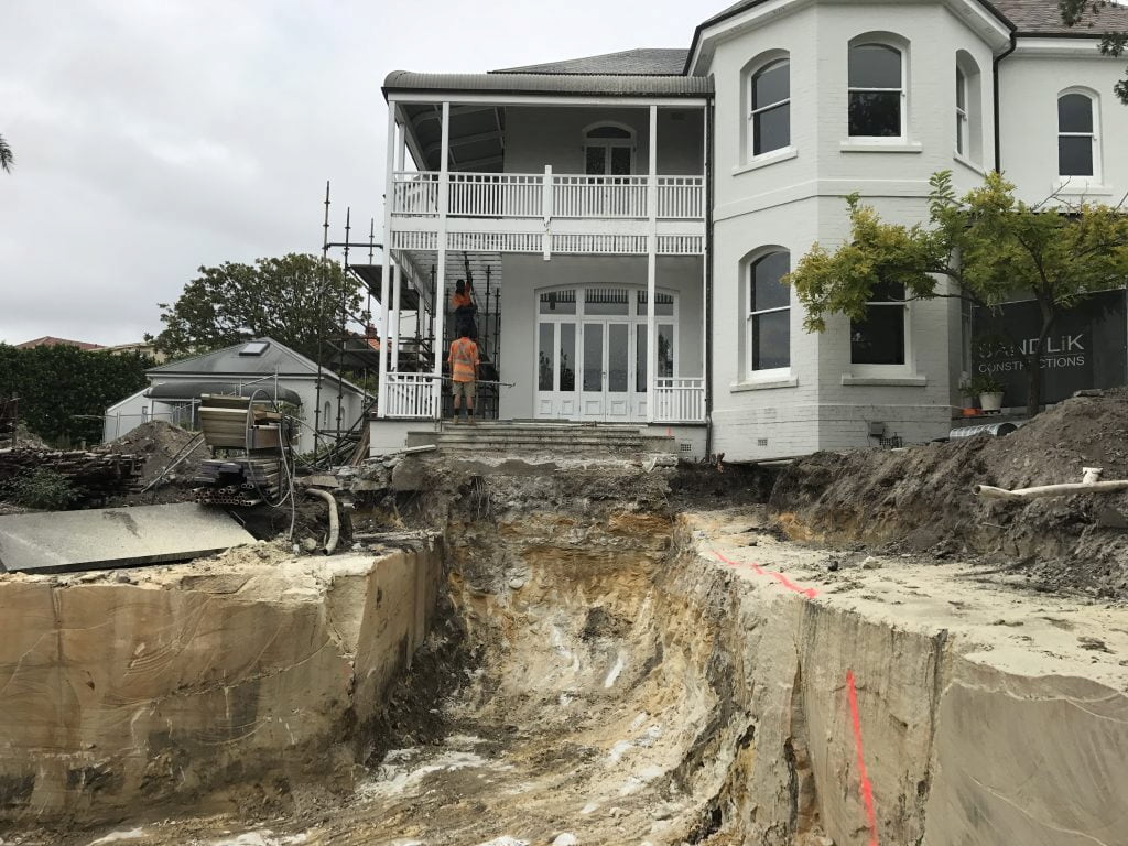
Preparing to tunnel up under the house
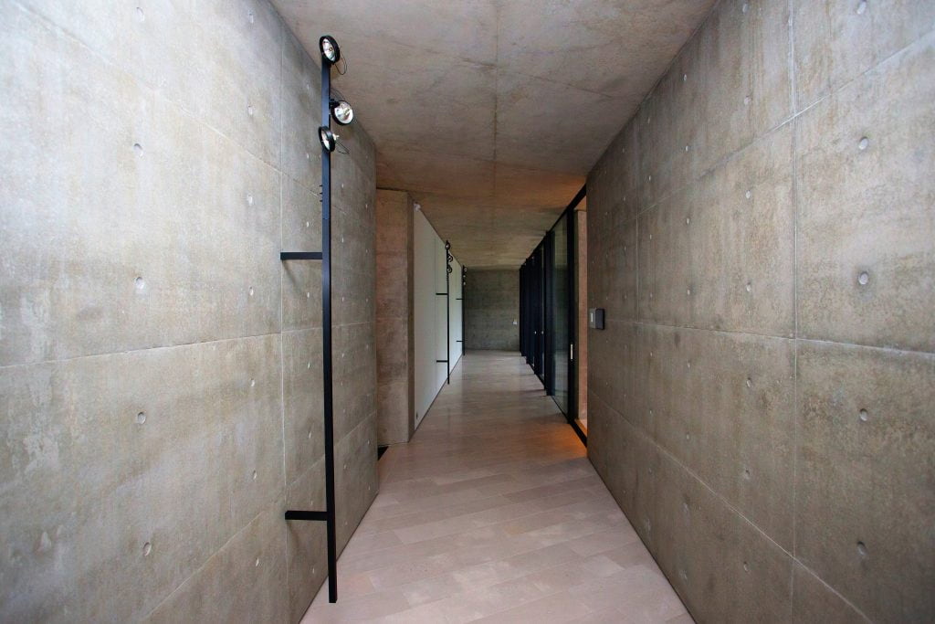
The finished tunnel from the pavilion to the house